Clearance Is a Design Feature
Every moving joint needs a gap your printer can reliably resolve. Too small and the parts fuse; too large and the joint rattles and wears. Use the tolerance coupon described in the CAD guide, printed in the same material and orientation as the mechanism. Gaps that print cleanly on vertical walls may fuse on horizontal surfaces, where layers droop slightly, so test both if your joint has both.
Print-in-Place Hinges
Print-in-place hinges are assembled by the printer itself: knuckles interlock around a pin with a gap all round. Print them with the pin axis parallel to the bed so layers wrap around the pin rather than stacking along it, which would make the pin snap at the first twist. Give the gap a chamfered or cone-shaped profile underneath so the overhang self-supports. After printing, work the hinge gently through its range to break any light bonding.
Cantilever Snap Fits
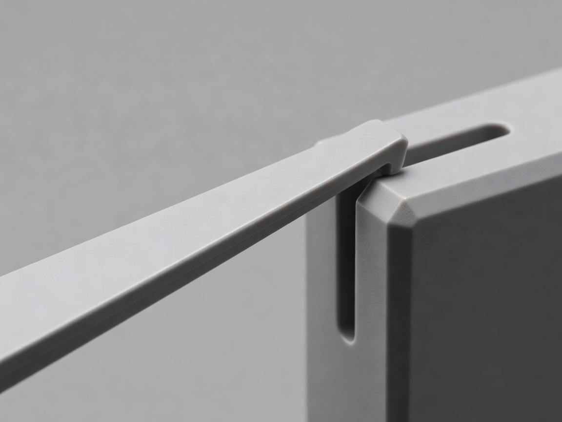
A snap fit is a beam that bends during assembly and springs back behind an undercut. The governing value is strain at the root of the beam: if assembly bends the beam beyond what the material tolerates, it whitens, cracks or takes a permanent set. The classic design reference here is the snap-fit guidance published by Bayer MaterialScience for moulded plastics; the principles carry over, but printed parts need extra margin because layer bonds are weaker than moulded material.
- Print the beam flat so bending stress runs along the extruded lines.
- Taper the beam toward the tip to spread strain more evenly.
- Add a generous fillet at the root — sharp internal corners concentrate stress.
- Lengthen the beam before thickening it; strain drops as length rises.
Living Hinges
Polypropylene is the textbook living-hinge material, and some printed PP and TPU handle repeated flexing well. In PLA or PETG, a thin flexing web will usually fatigue and crack after relatively few cycles. If you need a fold-flat feature in a stiff material, consider a pinned hinge or a compliant flexure with a longer, thicker active length instead.
Gears and Power Transmission
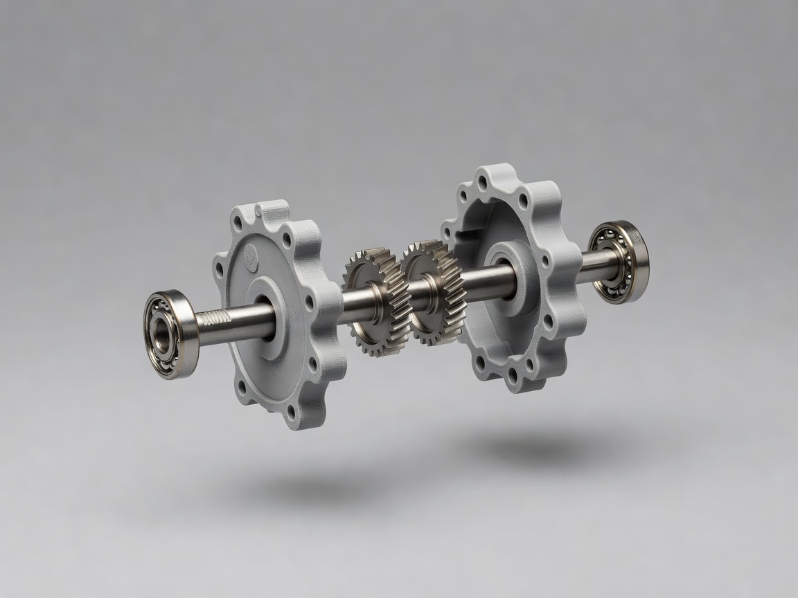
Printed gears work well at low loads and speeds. Use a standard involute profile with a 20° pressure angle, generated by a plugin or library rather than drawn by hand, and choose a module large enough for the nozzle to resolve the teeth — module 1 and above is a sensible start with a 0.4 mm nozzle. Herringbone gears are self-centring and print without support. Nylon and PETG resist wear better than PLA, and a light dry lubricant helps.
Fasteners, Inserts and Bearings
Machine screws should not bite directly into repeatedly opened plastic. Brass heat-set inserts, pressed in with a soldering iron, give durable threads; model the hole to the insert maker's recommended size. Captive hex nuts in a modelled pocket are a simple alternative. For press-fit bearings such as the common 608, add small crush ribs inside the bore so the fit relies on the ribs deforming rather than on the whole bore being exact.
Compliant mechanisms replace pins and springs with flexing geometry. The Compliant Mechanisms Research Group at Brigham Young University, led by Larry Howell, has published extensively on the topic, and his book Compliant Mechanisms is a thorough introduction.
Iteration Log — Battery Door Snap
- Rev A · PLA, 1.2 mm beam
Whitened at root on first assembly; cracked on cycle 4. - Rev B · Beam lengthened 8 → 14 mm
No whitening; 60 cycles before crack at a sharp root corner. - Rev C · 1 mm root fillet, PETG
500 cycles, no visible damage. Retention force still acceptable.
“A mechanism is a promise to repeat. Test it as many times as the user will.”Bench rule
If a joint fails during testing, the fracture tells a story — read it before redesigning.